Building an Info Portal Wi-Fi network
The use of Info Portals often leads to having two or more Wi-Fi signals broadcast by a single Wireless Router. As for the Wi-Fi hotspots, it's often necessary to expand the area covered by Wi-Fi signal using the Access Points.
Let us examine, in the case of using a router with OpenWRT firmware, two different ways to expand the wireless network in the presence of two SSID (Hotspot + Info Portal).
The first step is to disable the flag "Separate from the WiFi Lan" in the location settings on My Wi-Fi Service control panel. In this way the two Wi-Fi signals will be output from the antennas of the wireless router and will be created two VLAN (one for each wireless network) on which the Hotspot networks (VLAN1) and Info Portal (VLAN2) will be available.
At this point, to repeat the wireless signal, we can use an Access Point for each SSID or a single Access Point that repeats all the signals.
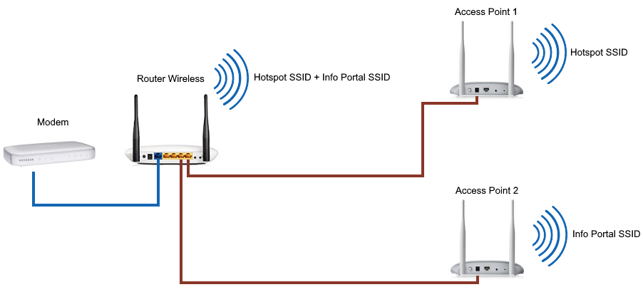
Use of an access point for each SSID
As can be seen from the above diagram, each access point is connected to a different port on the router.
In order to use this mode is necessary that every VLAN is
associated with a specific LAN port on the router. This is achieved by inserting the following script under "Additional Script" of the location:
for ind in 3 2 1 0
do
uci -q delete network.@switch_vlan[$ind]
done
for vlanid in 1 2 3 4
do
uci add network switch_vlan
uci set network.@switch_vlan[-1].device="switch0"
uci set network.@switch_vlan[-1].vlan=`expr $vlanid - 1`
uci set network.@switch_vlan[-1].vid=$vlanid
uci set network.@switch_vlan[-1].ports="0t $vlanid"
done
uci commit
This setup is fairly simple but has the drawback of requiring two access points and two different cabling.
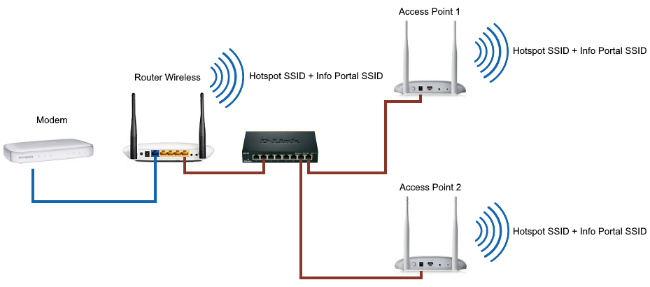
Repetition of all the SSID on each Access Point
Thanks to this mode, slightly more complex than the previous one, you can use a single access point to repeat all the SSID.
Additional Script:
for ind in 3 2 1 0
do
uci -q delete network.@switch_vlan[$ind]
done
for vlanid in 1 2 3 4
do
uci add network switch_vlan
uci set network.@switch_vlan[-1].device="switch0"
uci set network.@switch_vlan[-1].vlan=`expr $vlanid - 1`
uci set network.@switch_vlan[-1].vid=$vlanid
uci set network.@switch_vlan[-1].ports="0t 1t 2t 3t 4t"
done
uci commit
The image above shows how access points are connected to any LAN port, via a switch, with a single Ethernet cable.
This configuration is possible because the previous script assigns different ID (from 1 onwards) on all VLAN on the router and set all ports as TAGGED.
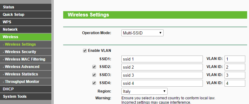
To complete the setup you must also configure the Access Point in "Multi-SSID" mode, and assign different SSID for each VLAN based on their ID.
Let's see how to do this with some very popular devices:
-
TP-Link 701/801/901: In Wireless | Settings, go to "Operation Mode" selecting "Multi-SSID" and assign a VLAN ID to each SSID starting from value 1.
- Ubiquiti antennas with UniFi firmware: open the control software UniFI, click on Settings | Wireless Newtork and add other Wi-Fi networks by enabling the VLAN and entering the SSID and the related VLAN ID (2,3,4 ..). Afterwards click on "Site" and disable the option "Enable monitor connectivity and wireless uplink".
Router Mikrotik
Using Mikrotik routers, in "location" menù we can choose the ethernet ports for Hotspot and Info Portal networks. The assigned ports changes based on the configuration used:
- Configuration with an Access Point for each SSID: in this case, for example, we can set the ether3 port as Hotspot and the ether4 for the Info Portal, then connect the two access point to these ports.
-
Repeating of all SSID on any Access Point: using only one Access Point, it will be necessary to execute the following commands before you execute the configuration script:
/interface vlan add name=vlan-1 vlan-id=10 interface=ether4 disabled=no
/interface vlan add name=vlan-2 vlan-id=20 interface=ether4 disabled=no
/interface bridge add name=br-vlan1 disabled=no
/interface bridge add name=br-vlan2 disabled=no
/interface bridge port add interface="vlan-1" bridge="br-vlan1" disabled=no
/interface bridge port add interface="ether2" bridge="br-vlan1" disabled=no
/interface bridge port add interface="vlan-2" bridge="br-vlan2" disabled=no
/interface bridge port add interface="ether3" bridge="br-vlan2" disabled=no
The previous script will create two VLAN networks (with ID 10 and 20) and will connect them in bridge mode with ether2 and ether3 ports.
In location settings we have to type the ports br-vlan1 for the Hotspot e br-vlan2 for the Info Portal.
The switch, to which are connected the Access Points, must be connected to the ether4 port.


